RDS-PS: The Flexible Standard for Modern Power Supply Systems
The Reference Designation System for Power Supply Systems (RDS-PS) is the IEC 81346-10 coding standard that brings the full ISO 81346 framework to renewable energy and grid assets. SøDera helps operators and EPCs build the project-specific specifications that turn this flexibility into operational value.
"RDS-PS is the missing link for the energy transition. Its strength is not that it tells you what to do, it is that it gives you a framework to architect your own data. But that freedom comes with responsibility: someone has to write the specification, and someone has to govern it."
Søren Christensen · Co-founder & CEO, SøDera
Understanding the standard
What is RDS-PS?

RDS-PS, the Reference Designation System for Power Supply Systems, is a structured, object-oriented coding system used to identify every system, component, signal, and document in a power supply asset. It assigns each object a unique, machine-readable address that remains consistent from initial design through decades of operation.
RDS-PS is defined by IEC 81346-10 as a domain-specific application of the ISO/IEC 81346 reference designation series. It is designed for the full breadth of modern power supply systems; offshore and onshore wind, solar plants, battery storage, substations, transmission infrastructure, and distributed generation. Where its predecessor RDS-PP was built around the operational reality of large centralised power plants, RDS-PS was conceived for the modular, distributed, and rapidly evolving architecture of the energy transition.
The defining characteristic of RDS-PS is its deliberate flexibility. IEC 81346-10:2022 explicitly states that "the reference designation is not bound to a fixed structural pattern." Where RDS-PP enforces consistency through fixed syntax and predefined system boundaries, RDS-PS hands that responsibility to the user. As long as the correct classification codes from the published tables are used and the ISO 81346 rules are respected, each operator is free to define a breakdown that fits their assets and business purpose. This is not a weakness of the standard, it is an intentional design choice.
Where it comes from
From ISO 81346 to RDS-PS: a standards-driven evolution
RDS-PS sits within a coherent family of international standards developed under the joint stewardship of ISO and IEC. The foundation is laid by ISO/IEC 81346-1, which defines the general principles of reference designation, and ISO/IEC 81346-2, which provides the classification of objects by their intended purpose or function.
Building on this foundation, IEC 81346-10 introduced the first domain-specific application of the framework, initially as RDS-PP for power plants, and subsequently revised into RDS-PS for the broader category of power supply systems. The 2022 edition of IEC 81346-10 is the current authoritative reference. Unlike its predecessor, it does not prescribe how breakdowns should be structured; it provides the rules, the classification tables, and the syntax, and leaves the structural decisions to the implementing organisation.
Because this flexibility creates a risk of inconsistency between organisations, parts of the industry have moved to develop shared application guidelines on top of the bare standard. The most significant of these is the TIM Wind working group, which has developed application guidelines for wind power plants. These guidelines effectively create a shared foundation for implementing RDS-PS in the wind sector while preserving the underlying flexibility intended by IEC 81346-10.
Clean aspects in RDS-PS
One of the most important differences between RDS-PS and RDS-PP is how the standard treats aspects. RDS-PS enforces aspect cleanliness: function, product, and location are kept strictly separate, each described by its own designation drawn from its own classification hierarchy. They are never mixed within a single block.
Function aspect
What the object does. The function aspect describes the intended purpose of an object, what it is meant to achieve in the system. Classified through the Table B.1 / B.2 / IEC 81346-2 Table 3 hierarchy. Used in P&IDs, control logic, alarm lists, and SCADA tags.
Product aspect
What the object physically is. The product aspect identifies a specific piece of hardware, a particular pump, transformer, switchgear, or sensor, independent of where it sits in the function structure. Used in datasheets, procurement, spare parts catalogues, and installation drawings.
Location aspect
Where the object is situated. The location aspect describes the physical or geographic position of the object. Classified through its own parallel hierarchy: Table C.1 / C.2 / IEC 81346-2 Table 4. Used in layout drawings, access planning, and maintenance routing.
The principle is simple: each aspect answers exactly one question and draws codes only from its own classification source. Function and location each have their own three-level pyramid of classification tables, described in detail below. This separation is what makes RDS-PS suitable for digital twins and for systems where the same physical object must be queried by purpose, by hardware type, and by location interchangeably.
How the classification works
Two parallel pyramids: function and location
RDS-PS classifies objects through two parallel three-level pyramids. The function aspect uses one pyramid; the location aspect uses another. Within each pyramid, the abstraction level decreases as the number of letters in the code increases, a single letter denotes the highest level of abstraction, and three letters denote the most specific.
The diagram below shows both pyramids and the source tables for each level.
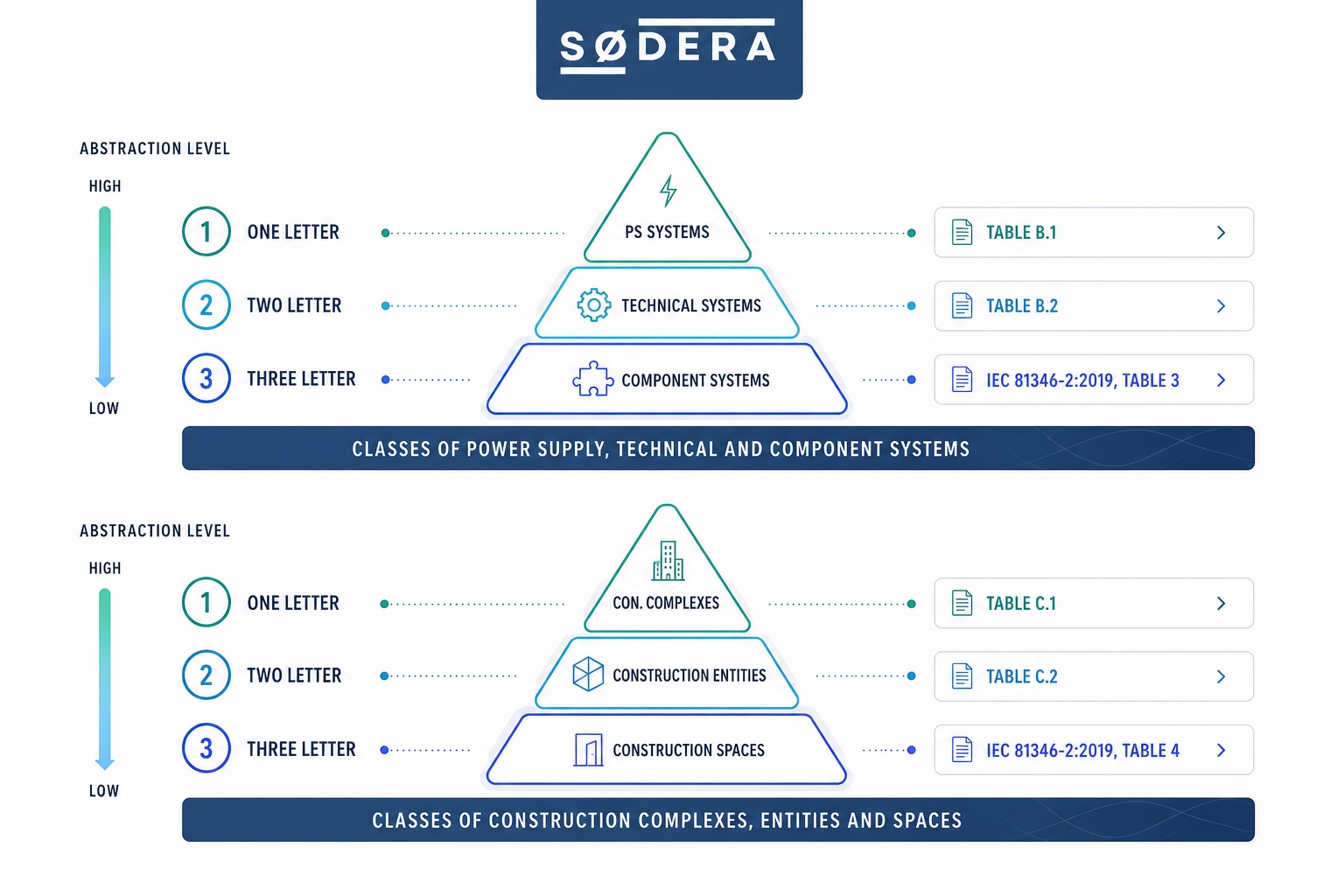
Function aspect classification
PS systems
Source: Table B.1, highest abstraction level
Technical systems
Source: Table B.2
Component systems
Source: IEC 81346-2:2019, Table 3, lowest abstraction level
Location aspect classification
Construction complexes
Source: Table C.1, highest abstraction level
Construction entities
Source: Table C.2
Construction spaces
Source: IEC 81346-2:2019, Table 4, lowest abstraction level
The codes drawn from these tables are then combined according to the ISO 81346 syntax rules into a complete reference designation. Because the structure between levels is not fixed by IEC 81346-10 itself, two operators classifying the same physical asset may produce different valid designations. This is why a project-specific designation specification, and ideally an application guideline such as TIM Wind, is essential to operational consistency.
Worked example, the same transformer system
Consider a transformer system in a substation. The physical asset is identical. The designation depends on the standard applied, and, in the case of RDS-PS, on the project-specific specification.
Both RDS-PS designations comply with IEC 81346-10. The difference reflects different structural interpretations of the same asset. RDS-PP enforces consistency. RDS-PS enables customisation, but only delivers consistency when supported by a clear project specification or industry application guideline.
Where it is applied
Built for distributed, modern energy assets
RDS-PS is designed for the full scope of modern power supply systems. Its flexible structure makes it particularly well suited to assets that are modular, repeating, and geographically distributed, characteristics that define the renewable energy transition. Offshore and onshore wind farms, utility-scale solar plants, battery energy storage systems, transmission substations, and distributed generation portfolios are all natural applications.
In the wind sector, the TIM Wind application guidelines have created a shared foundation for implementing RDS-PS across vendors, operators, and EPCs. The guidelines preserve the flexibility of IEC 81346-10 while providing enough convention to make designations comparable across the industry. For greenfield wind projects, RDS-PS is increasingly the default choice.
Because RDS-PS designations are aspect-clean and lifecycle-stable, they integrate naturally with SCADA platforms, CMMS systems, document management systems, and asset performance management tools. This integration is what makes RDS-PS a foundational prerequisite for digital twins. Without unambiguous, aspect-separated designation, plant-level sensor data, maintenance records, and engineering documents cannot be reliably joined across systems. RDS-PS provides the linking key.
For asset owners with mixed portfolios, for example renewable plants alongside legacy thermal stations designated under RDS-PP or KKS, RDS-PS provides a forward-compatible target architecture. The migration is non-trivial because the systems are not backward-compatible, but the destination is a single, IEC-compliant designation framework that can grow with the portfolio.
From the field
Common RDS-PS implementation pitfalls
Most RDS-PS problems are not problems with the standard. They are problems with how its flexibility is handled. We see the same handful of issues across asset owners, EPCs, and OEMs.
Treating flexibility as the absence of rules
IEC 81346-10 deliberately leaves structural decisions to the user, but those decisions still need to be made, and documented. We see projects where "RDS-PS compliant" effectively means "anything goes," with no project specification governing how the tables are applied. The result is internal inconsistency that defeats the purpose of standardisation entirely.
Ignoring the classification tables
Some implementations invent project-specific codes rather than drawing from Tables B.1, B.2, C.1, C.2, and the relevant IEC 81346-2 tables. This breaks cross-fleet comparability and undermines the entire reason for adopting an international standard. The tables are not optional decoration, they are the foundation of the framework.
Mixing function and location aspects
RDS-PS enforces aspect cleanliness: function (=) is drawn only from the function pyramid, location (+) only from the location pyramid. We frequently see implementations where these get blended into a single block, often as a hangover from RDS-PP habits or in-house tagging schemes. This destroys the queryability that makes RDS-PS valuable.
Choosing RDS-PS without choosing an application guideline
For wind power plants, the TIM Wind application guidelines provide the convention layer that IEC 81346-10 deliberately omits. Choosing RDS-PS without choosing, or writing, an application guideline leaves an organisation with all of the obligations of standardisation and none of its benefits.
No governance after the design phase
RDS-PS works only if someone owns it through the asset lifecycle. We see projects where the designation specification was carefully built during design and then degraded over years of operations because no one was responsible for change control. The codes drift, the project specification falls out of date, and the digital twin slowly stops being trustworthy.
Our methodology
How SøDera implements RDS-PS
We work alongside your engineering team to turn the flexibility of IEC 81346-10 into a concrete, documented, and governable designation framework, whether you are specifying it on a greenfield wind farm or migrating an existing fleet to the standard.
Specification definition
Defining the project-specific RDS-PS designation specification: which application guideline applies (TIM Wind or other), how the breakdown structure is built, how the aspects are kept clean, and how deviations are managed. This is the foundation document of the entire framework.
Classification mapping
Mapping your equipment to Tables B.1, B.2, C.1, C.2, and the relevant IEC 81346-2 tables with full traceability. Where the published tables do not cover a specific asset type, we document the extension rules so they remain compliant with the standard.
Engineering integration
Embedding RDS-PS into your engineering tools, P&ID software, electrical CAD, and instrument indexes, so that designations are generated and validated automatically rather than typed by hand. Aspect cleanliness is enforced at the tool level, not left to discipline.
SCADA and CMMS integration
Ensuring RDS-PS designations flow cleanly into your SCADA system, CMMS, and document management platform. The tag becomes the linking key across every operational system, enabling true portfolio-wide visibility.
Legacy migration
For existing assets, systematically mapping legacy tags (RDS-PP, KKS, in-house schemes, OEM-specific codes) to RDS-PS with full traceability. Because RDS-PS is not backward-compatible with RDS-PP, the migration is deliberate work, but nothing is lost, and every change is documented.
Training and governance
Hands-on training for the engineers, document controllers, and maintenance technicians who will use RDS-PS daily, combined with governance procedures that keep the specification clean over decades of operations.
Why partner with us
Hands-on RDS-PS experience, not theoretical advice
SøDera works on real wind and power supply projects with real engineering teams. We bring direct experience of what goes wrong when the flexibility of IEC 81346-10 is mishandled, and what it takes to put it right. We do not consult on RDS-PS from a standards document. We apply it.
Built for distributed assets
RDS-PS is designed for the modular, repeating structure of renewable assets. Our implementation frameworks are built around this reality, not adapted from conventional power plant practice.
Aspect-clean designation discipline
Function, product, and location aspects applied with the rigour IEC 81346-10 requires, drawn from the correct classification tables and never mixed across blocks.
Lifecycle data continuity
Designations that survive from initial concept through commissioning, operations, and decommissioning, linking every system in between under a single specification.
Digital twin foundation
A compliant RDS-PS framework is a prerequisite for any meaningful digital twin. We build the foundation that makes downstream digitalisation possible.
Frequently asked questions
RDS-PS, answered
What is RDS-PS?
RDS-PS, the Reference Designation System for Power Supply Systems, is a standardised, object-oriented coding system defined by IEC 81346-10 for the unique identification of every system, component, signal, and document in a power supply asset. It is built directly on the ISO/IEC 81346 series and is deliberately flexible: it does not prescribe a fixed structural pattern, giving operators the freedom to define the breakdown that best fits their assets.
Where does RDS-PS come from?
RDS-PS was introduced through IEC 81346-10 as a domain-specific application of the ISO 81346 series for power supply systems. It builds on the same theoretical foundations as RDS-PP (ISO 81346-1 and ISO 81346-2) but takes a different design philosophy. Where RDS-PP was developed by VGB PowerTech with fixed syntax and predefined boundaries, RDS-PS was developed as an open framework that allows each project or operator to define their own breakdown structure within the ISO 81346 rules.
What is the difference between RDS-PS and RDS-PP?
RDS-PP is the VGB-maintained system with fixed-syntax breakdown levels and dedicated classification libraries (VGB-B 101, VGB-B 102). RDS-PS, defined by IEC 81346-10, is deliberately more flexible in syntax and uses its own classification tables (B.1, B.2, C.1, C.2, plus IEC 81346-2). Both share the same ISO/IEC 81346 foundations but apply different rules. RDS-PP enforces consistency; RDS-PS enables customisation. For a deeper comparison, see our article RDS-PP vs RDS-PS.
What classification tables does RDS-PS use?
RDS-PS uses two parallel three-level classification hierarchies. For the function aspect: Table B.1 for one-letter PS systems, Table B.2 for two-letter technical systems, and IEC 81346-2:2019 Table 3 for three-letter component systems. For the location aspect: Table C.1 for one-letter construction complexes, Table C.2 for two-letter construction entities, and IEC 81346-2:2019 Table 4 for three-letter construction spaces. Abstraction decreases as the number of letters increases.
Is RDS-PS backward-compatible with RDS-PP?
No. RDS-PS is not backward-compatible with RDS-PP. The two systems use different classification tables, different syntax rules, and different structural philosophies. The same transformer system that would be designated =T001 ATA10 in RDS-PP might be designated =B1.KF1 in one RDS-PS implementation and =B1.JE1.KF1 in another. Migrations between the two systems require careful mapping and full traceability.
How long does it take to implement RDS-PS on a wind farm?
A greenfield wind farm with RDS-PS specified at design stage typically requires three to six months of structured implementation work. Because RDS-PS requires the operator to define their own specification, the upfront work is more substantial than for RDS-PP. A retrofit on an existing operational asset typically takes six to eighteen months depending on fleet size, data quality, and the depth of legacy tagging that needs to be mapped. It also depends on the level of detail required. Reach out to us and we can advise you from the start.
From our team